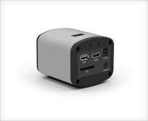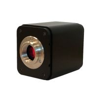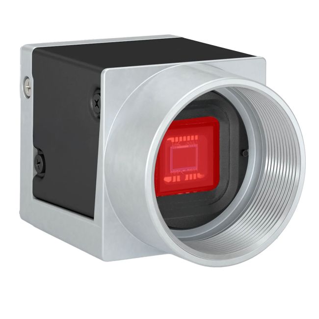
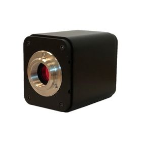
CMOS USB Microscope Camera

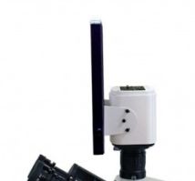
Our compact CMOS USB color cameras are a perfect option for a low-profile, space saving design—particularly in high movement microscopy setups (e.g. portable/rollable surgical microscopes, articulating arm setups, etc). Offered in 1/1.8”, 1/2", and 1/3” sensor sizes, these small yet powerful cameras will give you high quality visibility, without compromising on space or cost.
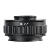
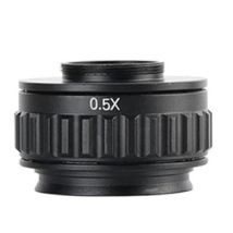
*C-mounts are required to pair with a trinocular microscope and are sold separately. Check out our c-mount options here.
Color CMOS USB Cameras
Options
| Order code | Description |
| USBCAM1-2 | CMOS USB Microscope Camera, 1/2" Sensor |
| USBCAM1-1-8 | CMOS USB Microscope Camera, 1/1.8" Sensor |
| USBCAM1-3 | CMOS USB Microscope Camera, 1/3" Sensor |
*Note: 506021 3.0USB is included with your USBCAM system.
Features
Simple design allows for a simple, hassle-free mounting to your microscope. Connect to a monitor source using a USB to visualize your subject. Offered in 1/1.8”, 1/2", and 1/3” sensor sizes.
- Auto functionality: Allows the camera to find the optimum settings for exposure time, gain, and white balance, for example. This simplifies camera integration into your application.
- Color Creation: This feature allows for correction of artifacts in color images without affecting the structures in the image.
- Image Adjustment: Adjust pixel values without loss of quality using Black Level, Digital Shift, and other standard features.
- Digital I/Os: Control the camera via trigger commands or use the camera to control components of your vision system, such as lighting or encoders.
- Information Utilization: Use additional information from Chunks and Events to optimize your automation.
- Intelligent Light Control (SLP): Control the lighting directly with the camera. By synchronizing the flash mode and adjusting the brightness levels, you can quickly achieve precise lighting conditions and shorten the development time of your application.
- Sequencer: Program sequential processes in the camera to control image acquisition and pre-processing in real time.
- Data Reduction: Use the Binning, Decimation, or ROI features for customized data reduction.
| SKU | VAR-506011 |
|---|
| Features | 506011 | 506012 | 506013 |
| Resolution | 1280 px x 1024 px (1.3MP) | 3088 px x 2064 px (6.4MP) | 1456 x 1088 (full resolution) / 1440 x 1080 (default resolution) – 1.6MP *You can change the resolution by changing the image ROI. |
| Sensor Type | onsemi PYTHON NOIP1SE1300A Progressive scan CMOSGlobal Shutte
| Sony IMX178LQJ-C Progressive scan CMOS Rolling shutter | Sony IMX273LQR-C Progressive scan CMOS Global shutter |
| Sensor Format | 1/2” | 1/1.8” | 1/3” |
| Effective Sensor Diagonal | 7.9mm | 8.92mm | 6.3mm |
| Pixel Size (H x V) | 4.8 x 4.8 µm | 2.4 x 2.4 µm | 3.45 x 3.45 μm |
| Frame Rate | 203 fps (at fast sensor readout mode) 169 fps (at normal sensor readout mode) | 59.6 fps (Device Link Throughput Limit Mode set to Off) 56.4 fps (default settings) | 227 fps |
| Mono / Color | Color | ||
| Pixel Format | *See Pixel Formats Data Sheet Under Resources | ||
| Image Data Interface | USB 3.0, nominal max. 5 Gbit/s (SuperSpeed) | ||
| Synchronization | Via hardware trigger Via software trigger Via free run | ||
| Exposure Time Control | Via hardware trigger Programmable via the camera API | ||
| Camera Power Requirements | ≈3.0 W (typical) @ 5 VDC ≈3.3 W (max.) | ||
| I/O Lines | 1 opto-coupled input line 1 opto-coupled output line 2 general purpose I/O (GPIO) lines | ||
| Lens Mount | C-mount | ||
| Size (L x W x H) | 29.3 x 29 x 29 mm (without lens mount or connectors) 48.2 x 29 x 29 mm (with lens mount and connectors) | ||
| Weight | 80g | ||
| Conformity | CE (includes RoHS), EAC, UKCA, UL Listed, FCC, GenICam 2.x (including PFNC 2.x and SFNC 2.x), IP30, USB3 Vision, REACH, KC *See conformity documentation in user manual | ||
| Software | Basler pylon Software Suite (version 4.0 or higher) Available for Windows, Linux x86, Linux ARM, macOS, and Android | ||
Spectral Response
506011

*The spectral response curve excludes lens characteristics, light source characteristics, and IR cut filter characteristics.
506012

*The spectral response curve excludes lens characteristics, light source characteristics, and IR cut filter characteristics.
506013

*The spectral response curve excludes lens characteristics, light source characteristics, and IR cut filter characteristics.
IR Cut Filter
Color cameras are equipped with an IR cut filter. The filter is mounted in a filter holder inside the lens mount.
The IR cut filter has the following spectral characteristics:
| Wavelength [nm] | Transmittance |
| 450–610 | Tmin > 90 % |
| 450–620 | Tavg > 93 % |
| 645 ± 10 | T = 50 % |
| 700–1070 | Tmax < 4 % |
| 690–1070 | Tavg < 1 % |
Mechanical Specifications
Camera Dimensions and Mounting Points:

Requirements
Environmental Requirements: Temperature and Humidity
| Housing temperature during operation | 0–50 °C (32–122 °F) |
| Humidity during operation | 20–80 %, relative, non-condensing |
| Storage temperature | -20–80 °C (-4–176 °F) |
| Storage humidity | 20–80 %, relative, non-condensing |
| Housing temperature according to UL 60950-1 | max. 70 °C (158 °F) |
| Ambient temperature according to UL 60950-1 | max. 30 °C (86 °F) |
Camera Power
You must supply camera power that complies with the Universal Serial Bus 3.0 specification. The camera's nominal operating voltage is 5 VDC, effective on the camera's connector.
Opto-Coupled I/O Input Line
| Voltage | Description |
| 30 VDC | Absolute maximum. This voltage must never be exceeded. Doing so may damage the camera and voids the warranty. |
| 0–24 VDC | Safe operating range. |
| 0–1.4 VDC | Indicates a logical 0 (with inverter disabled). |
| >1.4–2.2 VDC | Region where the logic level transition occurs; the logical state is not defined in this region. |
| >2.2 VDC | Indicates a logical 1 (with inverter disabled). |
- Minimum current: 5 mA
- Current draw: 5–15 mA
- If the camera is connected to a PLC device, Basler recommends using a cable that adjusts the voltage level of the PLC to that of the camera.
Opto-Coupled I/O Output Line
| Voltage | Description |
| 30 VDC | Absolute maximum. This voltage must never be exceeded. Doing so may damage the camera and voids the warranty. |
| 3.3–24 VDC | Safe operating range. |
| <3.3 VDC | Unreliable I/O output. |
- Leakage current: <60 µA. Actual leakage depends on operating temperature and production spread of electronic components.
- Maximum load current: 50 mA
- Minimum load current: Not specified. Consider the following:
- Leakage current will have a stronger effect when load currents are low.
- Propagation delay of the output increases as load currents decrease.
- Higher-impedance circuits tend to be more susceptible to EMI.
- Higher currents cause higher voltage drops in long cables.
General Purpose I/O Lines
| Voltage | Description |
| 30 VDC | Absolute maximum. This voltage must never be exceeded. Doing so may damage the camera and voids the warranty. |
| 0–24 VDC | Safe operating range. The minimum external pull-up voltage is 3.3 VDC. |
| 0–0.8 VDC | Indicates a logical 0 (with inverter disabled). |
| >0.8–2.0 VDC | Region where the logic level transition occurs; the logical state is not defined in this region. |
| >2.0 VDC | Indicates a logical 1 (with inverter disabled). |
- Current draw (high-level): <100 μA
- Sink current: Your application must be able to accept 2 mA sink current from the GPIO input line without exceeding 0.8 VDC.
Operation as Output
| Voltage | Description |
| 30 VDC | Absolute maximum. This voltage must never be exceeded. Doing so may damage the camera and voids the warranty. |
| 3.3–24 VDC | Safe operating range. |
| <3.3 VDC | Unreliable I/O output. |
- Internal pull-up resistor: ≈2 kΩ, with open collector. Many applications will have to provide an additional pull-up resistor.
- Residual voltage ("on" state): ≈0.4 VDC at 50 mA and 25 °C (77 °F) housing temperature. Actual residual voltage depends on operating temperature, load current, and production spread of electronic components.
- Leakage current: <60 µA. Actual leakage depends on operating temperature and production spread of electronic components.
- Maximum load current: 50 mA
- Minimum load current: Not specified. Consider the following:
- Leakage current will have a stronger effect when load currents are low.
- Propagation delay of the output increases as load currents decrease.
- Higher-impedance circuits tend to be more susceptible to EMI.
- Higher currents cause higher voltage drops in long cables.
Cable Requirements
USB 3.0 Cable
- Use a high-quality USB 3.0 cable with a Micro-B plug.
- To avoid EMI, cables must be shielded, as specified in the USB 3.0 standard.
*It is recommended to use the USB 3.0 cable included with the camera
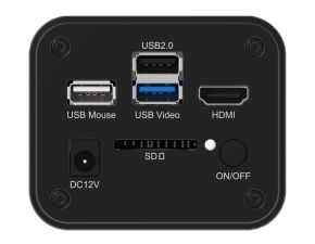
Physical Interface

Connector Pinout

| Pin | Line | Function |
| 1 | Line 3 | General purpose I/O (GPIO) line |
| 2 | Line 1 | Opto-coupled I/O input line |
| 3 | Line 4 | General purpose I/O (GPIO) line |
| 4 | Line 2 | Opto-coupled I/O output line |
| 5 | - | Ground for opto-coupled I/O lines |
| 6 | - | Ground for General Purpose I/O (GPIO) lines |